One basic thing to consider when doing stuff on the Arduino is the usage of the input and output pins.
The Arduino has 14 digital I/O pins, each configurable as input or output, and 6 analog inputs, so there is a hard limit to the amount of pins you have available. So, a basic plan is needed for this little project to avoid too many design errors and reconfigurations.
We need a lot of pins for this: One 7-segment LED display needs 7 pins (plus ground), and I wanted at least 3 displays to be able to show the PWM values of the RGB LED (0 to 255) in decimal numbers. So, we would need 3 x 7 = 21 output pins for the display alone! In order to get all 3 displays connected, we need to multiplex the outputs needed to control one display. Using multiplexing, I was able to control 4 displays using the same set of 7 output pins to control the actual number displayed, and 4 additional output pins to switch each display element on or off via transistors on the ground line. By switching fast enough through the elements, its looks to the human eye as if all 4 displays were on all the time.
So, let's recount: 11 pins for the displays (7 control pins, 4 on/off pins), that only leaves me with 3 digital I/O pins, which we need to control the 3 individual colors of the RGB LED. All digital pins are used up already!
Where to connect the slide potentiometer and the 2 buttons to? For the potentiometer, the answer is easy: Using it as a voltage divider, it needs to be connected to +5V and ground, and to one analog input pin on the Arduino, thus giving me a range from 0-1023 as readings from my Arduino code. Neat.
The buttons are a little bit more complex: As we only have analog input pins left, we need to connect the buttons using these. This by itself is not a problem really, you just have to remember to use AnalogRead() instead of DigitalRead() in your code when reading a button's state. Using standard C logic, we just treat an analog reading of 0 as false / LOW, and any value above 0 as true / HIGH (pretty much the same as the LOW and HIGH keywords used in the Arduino framework).
You just have to make sure that the value read from the analog pin is > 0 when the button is pressed, and is 0 when the button is released (or the other way around). As most push-buttons only have a closed or opened state, this means using pull up or pull down resistors on the input circuit.
(Explanation of pull up/pull down here.)
As the ATmega328 hast built-in pull up resistors for its digital inputs (which I always use if possible), I decided to use pull ups as well, as not having to use (and remember!) different logic. So, when the button is pressed it pulls the analog input pin to ground (a reading of 0). This means that a reading of 0 (or false, so to speak) from the analog pin means the button is pressed, and any other reading (or true) means the button is released. A bit the wrong the way around, but you get used to it.
Schematics for the pullup:
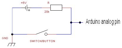
You could theoretically leave out the pull up resistor and +5V connection, and leave the pins "floating" when the button is not pressed, as they float way above ground/0. But this is not considered good practice and should be avoided. Please note that this is only an option on analog inputs, when treating them as digital input, and when using a pull-to-ground approach. On digital input this leads to erratic behavior, as the reading will switch between LOW and HIGH pretty much randomly.
This concludes the pin considerations, stay tuned for part 3 with full schematics, which should be up later today.
Update:
Part 3 is available: mood lamp - part 3 - schematics
Subscribe to:
Post Comments (Atom)
0 comments for this post